Monday, November 30, 2015

Project 2

ARCH 653_Project 2

Farshad Kheiri

This project has two steps:
1.       Creating a Dynamo model that is connected to the Revit file (project level).
2.       Making this model changeable with changes of the sun position.

In step one, first the model is connected to the Revit file

Input

Then we have some nodes to make the parameters changeable. This step is because of the YES/NO parameters that we already implemented in Revit file. These parameters would make the parameters changeable. Therefore, we needed Boolean nodes to assign YES value to them.
After this step, we can access and change the parameters of the façade. (The parameters graphical illustration and the nodes that are for changing each one of them is revealed in images below):

Parameters


Making the parameters changeable


Window Height


Window Width


Module Depth


X (horizontal placement of the window)


Z (vertical placement of the window)

The next step is to change the area of the windows based on the position of the sun. The area of the windows would increase by the increase of the sun altitude. For this reason, sun altitude and azimuth is gotten from the Revit file and a few scripts are added for the cases that sun is not above the horizon.


Getting Sun position, calculating shadows, and changing window areas


The window area in first floor is more sensitive to the position of the sun. Therefore, first the horizontal shadow is calculated:


Then the vertical shadow is calculated:


Then, the area which is counted twice would be subtracted:


Finally, a value (equal or more than one) would be calculated based on the shadow area on the window.


The point is that the area multiplier for the floors other than the first floor is a number between Zero to One; but in the first floor, the values would be 1 or greater than one. Consequently, Changes in the areas of the windows in the first floor would be more sensitive to the changes of the sun position than in other floors.

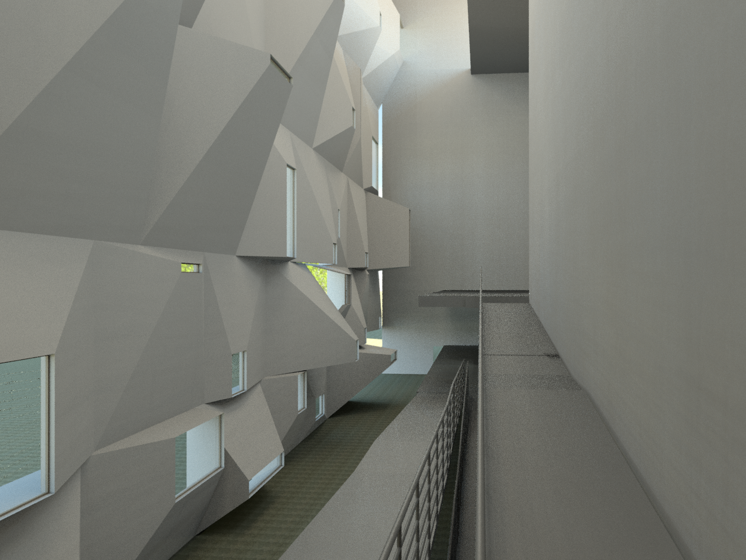
Here is some examples of the changes of the window area by changing the Sun position in the same day:

12:30 PM

2:30 PM

12:30 AM

Tuesday, November 3, 2015

Project One

Leon Auditorium

Technical Data:

Location: Avenida Reyes Leoneses, León, Spain. Architects: Luis M. Mansilla and Emilio Tuñón. Client: Regional Government of Castilla y León, Municipality of León.Collaborators: Andrés Regueiro, Fernando García-Pino, María Linares and Matilde Peralta.Structural engineers: Alfonso Gómez Gaite. Mechanical engineers: J.G. Asociados. Acoustic engineers: Higini Arau. Graphic design: Gráfica Futura. Construction managers: Luis M. Mansilla, Emilio Tuñón and Andrés Regueiro. Quantity Surveyor/Technical Architect: Santiago Hernán and Juan Carlos Corona. Competition: 1994. Design project: 1996. Work completion: 2002. Built area: 9.000 m2. General contractor: Auditorio UTE  (FCC/CRS). Photographer: Luis Asin

Source: http://mansilla-tunon-architects.blogspot.com/

Parametric Modeling


In this project, my goal was to make one of the facades of the Leon Auditorium parametric that enables us to manipulate and observe different design options easily.

Source: https://s-media-cache-ak0.pinimg.com/736x/96/14/b0/9614b0d2602c99cf47d4a0d9f3e1984f.jpg


For making the façade parametric, I started working by creating one cubic module.


This model is mainly consisted of a solid, created by Blend, and a Blend void object. There are some parameters assigned to these objects to make them adaptive to the changes.


Here is a screenshot of a part of the parameters in this level:


Then, the module was loaded to another family. In this step, parameters for controlling the parameters in each level was assigned to the series of modules.
Parameters:

Depth_Series: a “n” digit number that will assign values to the depth of the window in each component, from right to left.
Height_Series: a “n” digit number that will assign values to the Height of the window in each component, from right to left.
Width_Series: a “n” digit number that will assign values to the Width of the window in each component, from right to left.
X_Series: a “n” digit number that will assign values to the X of the window in each component, from right to left.
Z_Series: a “n” digit number that will assign values to the Z of the window in each component, from right to left.
X_Porition: a “n” digit number that will make each X values positive or negative (“1” for positive, other digits for negative).
Z_Porition: a “n” digit number that will make each Z values positive or negative (“1” for positive, other digits for negative).
Heght_n: the parameter that controls the height of the level
Width_n: the parameter that controls the Width of the components in the level

X & Z of the windows are in the center of the window.

Beside these, the user can choose some other options to change the façade parameters:

1.  Increasing the area of the whole components by choosing the relative option and assigning a value to the “Area_Multiplier”
2.  Changing the area based on depth
3.  Putting the values for Xs, and Zs manually.
Next step was uploading the previous family to a new family and creating the whole façade.


Part of the Family Type parameters in this level:


Also, the other parts of the building were modeled, first in mass modeling and then uploaded into the project.


The last step was to upload the façade family into the project.


Sample of instant parameters:


Sample of type parameters:


Here are some screenshots that show the parametric changes:


Interior Render:


Exterior Render:


Texas A&M University
ARCH_653
Project_1
Dr. Wei Yan

Farshad Kheiri